
[Redated after several addendums…]
I’ve got a brief break in courseware, so decided to do some ‘fun’ graphics. The Ice Plant piece earlier this year didn’t include the destination of the ice. So here’s a condensed version of the original set, with the destination added on.
= = = = =
How did the ice plant make its portable blocks of coldness? The method was unexpectedly complicated.
Here’s the coldroom, where the compressed and relatively cool ammonia is allowed to relieve its pressure and absorb heat from the water that will become ice.

What’s going on inside? We have a grid in the floor, over a pool of cold brine kept at -10 degrees by the evaporation coils. The brine is also agitated by a stirrer, not shown here. Polistra is filling one of the cans with water.

I’ve shown only one filled row for simplicity. All rows in the grid were occupied by cans, immersed in the cold and moving brine. The movement insured that each can was cooled equally, and also helped to shake out the air in the cans. Clear ice was considered a mark of quality.
These are the smallest available cans, 8 x 8 x 32, holding 50 pounds of ice. Most systems used larger cans. Each can has a graspable edge on top, which is the key to the mass production process.

Picking up and handling the cans was difficult. Not necessarily from the weight, since a typical workman could handle 50 pounds. The problem was getting out onto the floating grid and grabbing the slippery can. Machines like this air-driven hoist did the grabbing job, and workmen handled the cans after they were on solid ground. The hoist has spring-loaded tongs designed to snap onto the top edge of the can, and mechanisms to lift the tongs and slide the carrier horizontally.

After taking the can out of the grid, the ice had to be pulled out. This machine, known as the Thawing Apparatus, did the job. A box holds the can tightly while warm water sprays on the surface.

After the can expands, the Thawing Apparatus can be tilted to let the ice slide out of the can. Then the can is dropped back into the grid and refilled for the next load.
Route trucks would have loaded up at the loading dock:
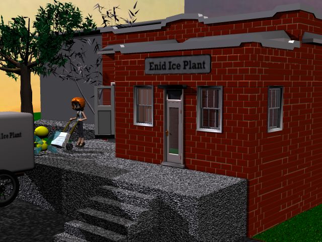

= = = = =
And then the truck would pull up in front of a house:

And the iceman would deliver the block to the housewife:

The interior of the icebox was simple. The ice block occupied an upper chamber, sometimes on top of the cabinet. Food occupied the other chambers.

Under the ice chamber is a drain pipe that leads down to the pan on the bottom. The pan had to be emptied every day, which was presumably done sometimes by the ice man. Some iceboxes had a spigot directly from the top chamber so you could run a hose to the nearest lower drain.

This rare round icebox was seen at the Cherokee Strip Museum website. It was owned by a rich family, perhaps more for display than practicality. Round stuff is NOT practical.
= = = = =
Adding on more, after halfway solving a puzzle. Architecture books often showed an Ice Door in an outer wall of a house so the iceman could place the block directly in the box. This implied that many iceboxes had an extra door in the back, but NONE of the iceboxes visible online have such a door. The real boxes in various antique sales and retro websites all have plain backs, and the few pictures in old trade journals are also one-sided. Was the back door a myth?
Finally found a sketch in Popular Science telling the home handyman how to build an Ice Door. The sketch shows the icebox equipped as I imagined:

So let’s complete the delivery in the fancy form. The iceman working on the outside would see this:

And the inside of the house would see this, if a mischievous Star had opened up the front door while the iceman was working through the back door.

